GPIO Usage
1. Introduction to GPIO
GPIO, short for General-Purpose Input/Output, is a common digital input/output interface in computers and embedded systems. It allows software to control the digital inputs and outputs of hardware, such as switches, sensors, LEDs, etc. GPIO is typically supported by pins on a chip or processor, which can be programmed to configure these pins as inputs or outputs, and their input status can be read or output status controlled through corresponding software commands.
2. GPIO Pin Number Calculation Method
RK3588 has a total of 5 GPIO banks: GPIO0~GPIO4, each of which is further numbered as A0~A7, B0~B7, C0~C7, D0~D7. The following formulas are commonly used to calculate the pin numbers:
 GPIO pin calculation formula: pin = bank * 32 + number

 GPIO group number calculation formula: number = group * 8 + X
For example, the calculation for GPIO3_B5: 32 3 + 1 8 + 5 = 109 ---> This means that GPIO3_B5 corresponds to the GPIO number gpio-109.
3. Multiplexing
In addition to the general input/output function, GPIO pins may have other multiplexing functions.
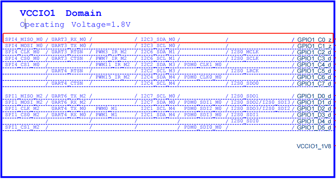
From the schematic, we can see that using GPIO1_C0 as an example, it has the following functions:
| func0 | func1 | func2 | func3 |
|---|---|---|---|
| GPIO1_C0 | I2C3_SDA_M0 | UART3_RX_M0 | SPI4_MISO_M0 |
In the system DTS configuration, GPIO1_C0 defaults to the I2C3_SDA_M0 function. If we want to multiplex GPIO1_C0 as the UART3_RX_M0 function, how should we do it?
- First, open the uart3 node and set the pinctrl configuration to uart3m0_xfer. The pinctrl configuration is the most critical configuration for GPIO multiplexing, and here it multiplexes GPIO1_C0 as the uart3 function.
&uart3 {
    pinctrl-names = "default";
    pinctrl-0 = <&uart3m0_xfer>;
    status = "okay";
};

&pinctrl {
    uart3 {
        /omit-if-no-ref/
        uart3m0_xfer: uart3m0-xfer {
            rockchip,pins =
                /* uart3_rx_m0 */
                <1 RK_PC0 10 &pcfg_pull_up>,   # Multiplex GPIO1_C0 as uart3_rx_m0
                /* uart3_tx_m0 */
                <1 RK_PC1 10 &pcfg_pull_up>;   # Multiplex GPIO1_C1 as uart3_tx_m0
        };
    };
};
- If you find that GPIO1_C0 is multiplexed as I2c3, disable it in the dts.
&i2c3 {
    status = "disabled";
};
In this way, we have multiplexed GPIO1_C0 as the UART3_RX_M0 function.
4. GPIO Debugging Methods
4.1 Read GPIO Status Information
The Debugfs file system is designed to provide developers with more kernel data for debugging purposes. The debugging of GPIO can also be done using the Debugfs file system to obtain more kernel information. The GPIO interface in the Debugfs file system is /sys/kernel/debug/gpio, and you can read the information from this interface as follows:
armsom@armsom:~$ sudo cat /sys/kernel/debug/gpio
gpiochip0: GPIOs 0-31, parent: platform/fd8a0000.gpio, gpio0:
 gpio-15  (                    |led_rgb_b           ) out lo
 gpio-20  (                    |reset               ) out lo ACTIVE LOW
 gpio-21  (                    |bt_default_wake_host) in  hi

gpiochip1: GPIOs 32-63, parent: platform/fec20000.gpio, gpio1:
 gpio-34  (                    |bt_default_rts      ) in  hi
 gpio-36  (                    |vcc3v3-pcie30       ) out lo
 gpio-40  (                    |camera-pwdn-gpio    ) out hi
 gpio-54  (                    |hdmirx-det          ) in  lo ACTIVE LOW
 gpio-58  (                    |vcc3v3-pcie2x1l0    ) out hi
 gpio-61  (                    |headset_gpio        ) in  hi

gpiochip2: GPIOs 64-95, parent: platform/fec30000.gpio, gpio2:
 gpio-78  (                    |vbus5v0-typec       ) out lo

gpiochip3: GPIOs 96-127, parent: platform/fec40000.gpio, gpio3:
 gpio-101 (                    |vcc-5v0-gpio-regulat) out hi
 gpio-102 (                    |bt_default_reset    ) out lo
 gpio-104 (                    |reset               ) out hi
 gpio-125 (                    |bt-wake-gpio-regulat) out hi

gpiochip4: GPIOs 128-159, parent: platform/fec50000.gpio, gpio4:
 gpio-130 (                    |wifi-diable-gpio-reg) out hi
 gpio-134 (                    |sbu1-dc             ) out lo
 gpio-135 (                    |sbu2-dc             ) out lo
 gpio-136 (                    |vcc5v0-host-regulato) out hi
 gpio-149 (                    |led_rgb_r           ) out lo

gpiochip5: GPIOs 509-511, parent: platform/rk806-pinctrl.9.auto, rk806-gpio, can sleep:
From the information read, we can see that the kernel lists the current status of the GPIO. For example, for the GPIO0 group, gpio-15 (GPIO0_B7) corresponds to the dts node led_rgb_b and outputs a low level (out lo).
4.2 View pinmux-pins
armsom@armsom:~$ sudo cat /sys/kernel/debug/pinctrl/pinctrl-rockchip-pinctrl/pinmux-pins
Pinmux settings per pin
Format: pin (name): mux_owner gpio_owner hog?
pin 0 (gpio0-0): (MUX UNCLAIMED) (GPIO UNCLAIMED)
pin 1 (gpio0-1): (MUX UNCLAIMED) (GPIO UNCLAIMED)
pin 2 (gpio0-2): (MUX UNCLAIMED) (GPIO UNCLAIMED)
pin 3 (gpio0-3): (MUX UNCLAIMED) (GPIO UNCLAIMED)
pin 4 (gpio0-4): fe2c0000.mmc (GPIO UNCLAIMED) function sdmmc group sdmmc-det
pin 5 (gpio0-5): feb20000.spi (GPIO UNCLAIMED) function spi2 group spi2m2-pins
pin 6 (gpio0-6): feb20000.spi (GPIO UNCLAIMED) function spi2 group spi2m2-pins
pin 7 (gpio0-7): (MUX UNCLAIMED) (GPIO UNCLAIMED)
pin 8 (gpio0-8): 6-0051 (GPIO UNCLAIMED) function hym8563 group rtc-int
pin 9 (gpio0-9): feb20000.spi (GPIO UNCLAIMED) function spi2 group spi2m2-cs0
pin 10 (gpio0-10): wireless-wlan (GPIO UNCLAIMED) function wireless-wlan group wifi-host-wake-irq
pin 11 (gpio0-11): feb20000.spi (GPIO UNCLAIMED) function spi2 group spi2m2-pins
pin 12 (gpio0-12): (MUX UNCLAIMED) (GPIO UNCLAIMED)
pin 13 (gpio0-13): fiq-debugger (GPIO UNCLAIMED) function uart2 group uart2m0-xfer
pin 14 (gpio0-14): fiq-debugger (GPIO UNCLAIMED) function uart2 group uart2m0-xfer
pin 15 (gpio0-15): leds gpio0:15 function leds group led-rgb-b
pin 16 (gpio0-16): (MUX UNCLAIMED) (GPIO UNCLAIMED)
pin 17 (gpio0-17): (MUX UNCLAIMED) (GPIO UNCLAIMED)
pin 18 (gpio0-18): (MUX UNCLAIMED) (GPIO UNCLAIMED)
pin 19 (gpio0-19): (MUX UNCLAIMED) (GPIO UNCLAIMED)
pin 20 (gpio0-20): sdio-pwrseq gpio0:20 function sdio-pwrseq group wifi-enable-h
pin 21 (gpio0-21): (MUX UNCLAIMED) gpio0:21
...
We can take pin 13 (gpio0-13): fiq-debugger (GPIO UNCLAIMED) function uart2 group uart2m0-xfer as an example:
The node name corresponding to gpio0-13 is fiq-debugger. This node is multiplexed as the debug serial function using the pinctrl configuration, and the pinctrl value is uart2m0-xfer.
5. GPIO Control
5.1 GPIO sysfs interface
Controlling GPIO in user space based on sysfs: The method of controlling GPIO through sysfs is mainly based on the GPIO control interface file provided by the kernel. In other words, it controls the corresponding gpio interface by reading and writing files in the/sys/class/gpio directory.
echo 109 > /sys/class/gpio/export                  # Export the corresponding GPIO
echo out > /sys/class/gpio/gpio109/direction       # Set the GPIO as output direction
echo 1 > /sys/class/gpio/gpio109/value             # Set high output level
cat /sys/class/gpio/gpio109/value                  # Get the current GPIO status, whether it is high or low level
echo 109 > /sys/class/gpio/unexport                # Release the requested GPIO
Note: Only when the GPIO3_B5 pin is not multiplexed by other peripherals, we can export it and then use.
5.2 GPIOD Usage
libgpiod is a character device interface, and GPIO access control is achieved by manipulating character device files (such as/dev/gpiodchip0) and providing command tools, C libraries, and Python encapsulation through libgpiod.
To use libgpiod, it is necessary to install the libgpiod library on the board:
#Install the gpiod command-line tool
sudo apt install gpiod
The usage of the gpiod tool is different from that of the sysfs interface. gpiod is measured in units of controllers and then detailed down to port numbers and index numbers, where gpiod uses two data points to determine the pins
| Pin | Controller | Port | Index | gpiod |
|---|---|---|---|---|
| GPIO3_C1 | 3 | C | 1 | 3 17(2x8+1) |
| GPIO3_B7 | 3 | B | 7 | 3 15(1X8+7) |
| GPIO1_B2 | 1 | B | 2 | 1 10(1x8+1) |
Taking GPO3_C3 as an example, the commonly used command lines are as follows:
gpiodetect                  # List all GPIO controllers
gpioinfo 3       # List the first set of controller pin groups
gpioset 3 19=0             # Set pin 3 of the first group controller number to low level
gpioget 3 19                  # Obtain the pin status of controller number 3 in the first group
gpiomon 3 19      # Monitor the pin status of controller number 3 in the first group
Not all pins can be controlled using libgpiod, such as some already used pins like LED